![]() Este circuito foi construido a pedido de um colega aeromodelista para ser instalado no seu avião equipado com um motor de 4 tempos.
Este circuito foi construido a pedido de um colega aeromodelista para ser instalado no seu avião equipado com um motor de 4 tempos.
O problema é que, nos modelos com motores a 4 tempos, por vezes torna-se complicado efectuar certas manobras acrobáticas sem que o motor vá abaixo em pleno voo devido ás caracteristicas destes motores. A solução passa por ligar a vela quando o acelerador desce para rotações baixas.
O circuito que construi irá controlar exactamente isso.
![]() This circuit was designed as a request by a fellow RC pilot and is to be installed in his airplane which is equipped with a four stroke engine.
This circuit was designed as a request by a fellow RC pilot and is to be installed in his airplane which is equipped with a four stroke engine.
The problem with these types of engines is that sometimes it's very hard to make certain acrobatic manouvers and not having an engine stop in mid air due to 4 stroke engine characteristics. The solution is to turn on the glow plug when the throttle drops bellow a certain point.
This circuit will control that.
O circuito foi projectado usando um microcontrolador 12F683. Ele monitoriza os sinais vindos de 2 canais diferentes.
Um desses canais é o canal do acelerador e vai ser responsavel por ligar ou desligar a vela do motor. A ligação é feita usando uma ficha Y em conjunto com a ficha do servo que irá controlar o carburador.
O outro canal é ligado directamente ao receptor num canal livre onde será usado um switch do radio para activar ou desactivar o circuito.
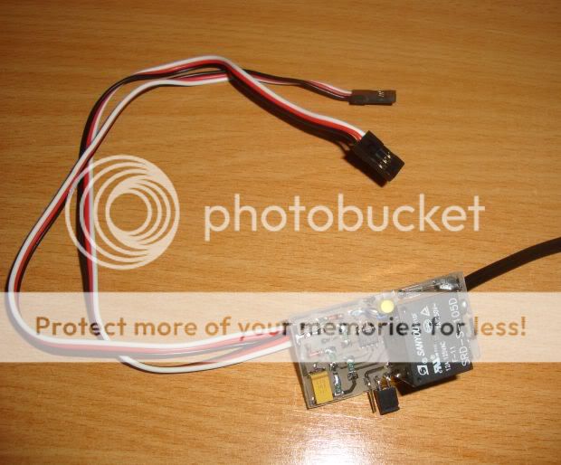
Na imagem abaixo pode ver-se o circuito sem a capa protectora exterior.
The circuit was designed using a 12F683 microcontroller. It reads the signals comming from 2 different channels.
One of these channels is the throttle channel and it will be responsable for turning on and off the glow plug. The connection is made using a Y connection together with the servo which controls the engine's carburator.
The other channel is connected directly to the receiver on a free channel and the switch on the radio will enable or disable the circuit.
The picture bellow shows the circuit assembled and without the external protecting cover.
Fig. 1
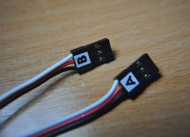
Ambas as fichas estão identificadas como A e B. A ficha A será ligada ao canal 3 e a ficha B será ligada ao canal extra.
Both inputs are labeled as A and B were A is for channel 3 and B for the spare channel.
Fig. 2
Uma vez que o sinal do canal 3 pode estar normal ou invertido, foi adicionado um jumper que permite ao circuito funcionar num ou noutro modo ( Fig. 3 ). Mudando a posição do jumper, vai reverter a acção do canal do motor.
Because the throttle channel can be set as normal ou inverted, i added a jumper which allows the circuit to operate in either way ( Fig. 3 ). Changing the jumper's position will reverse the action of the throttle channel.
Fig. 3
O circuito está equipado com um modo de programação, ou seja, é possivel definir em que ponto no percurso do stick do motor a vela irá ligar ou desligar.
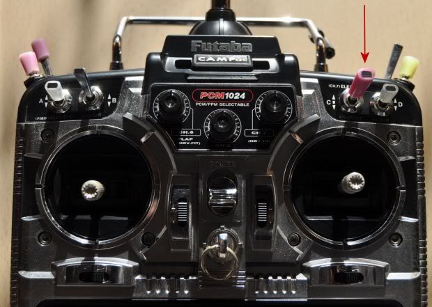
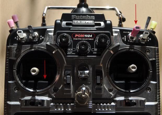
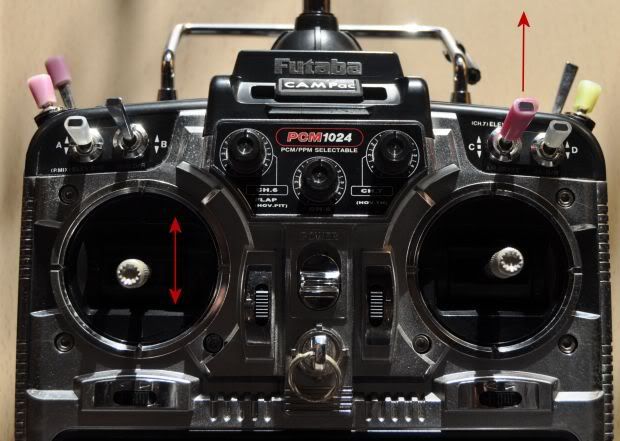
Para entrar no modo de programação, basta colocar o stick do acelerador no máximo e ligar a alimentação ao modelo.
O switch deverá fica na posição de desligado ( Fig. 4 ).
Neste caso foi utilizado o radio receptor FF8 da Futaba e o canal extra usado foi o canal 7.
The circuit is equipped with a setup mode which allows the user to define the exact position of the throttle stick that will change from on to off the glow plug.
To enter the setup mode, just place the throttle stick in max position and turn the power of the model on.
The switch must be in the off position at this time ( Fig. 4 ).
In this case it was used a Futaba FF8 receiver and the spare channel used was #7.
Fig. 4
Uma vez no modo de programação, movimentando o stick do acelerador é possivel ver em que zona a vela irá ligar ou desligar pelo led que irá acender ou apagar.
Para definir uma nova zona de transição, basta colocar o stick na posição pretendida e accionar o switch ( fig. 5 ). Nesse momento o led piscará indicando que está a gravar a posição na memoria. Durante essa altura deve-se movimentar o switch para a posição de desligado.
Once in the setup mode and moving the throttle stick it's possible to see the yellow led turning on and off indicating the areas were the glow plug will be turned on and off.
To set a new toggle position, just place the throttle stick were you need it to change the glow state and move the switch to the on position ( Fig. 5 ).
At that point the led will blink indicating that the position is being recorded. During that time the switch must return to the off position.
Fig. 5
Depois de gravada a posição, pode-se desligar a alimentação do modelo.
Esta posição irá ficar sempre gravada em memória mesmo sem alimentação.
After the position is set, the power can be turned off.
This setting will remain in memory even without any power being connected to the circuit.
Desde que o stick do acelerador não esteja acima de meio, o circuito não entrará em modo de programação ( Fig. 6 ).
Assim sendo, ligando a alimentação pode-se testar o circuito.
As long as the throttle stick is not placed above the middle position, the circuit will not enter the setup mode. ( Fig. 6 ).
Now the power can be turned on again and the circuit can be tested.
Fig. 6
Para accionar o circuito basta colocar o switch na posição LIGADO. Desta forma a vela irá ligar abaixo da posição definida e desligar acima da posição definida ( Fig. 7 ).
To enable the circuit just place the switch in the ON position. This way the glow plug will turn on below the set point and will turn off above the set point ( Fig. 7 ).
Fig. 7
Para desligar o circuito basta colocar o switch na posição DESLIGADO e desta forma, independentemente da posição do stick do acelerador a vela não ligará ( FIG. 8 ).
To disable the circuit just place the switch in the OFF position and this way, no matter where the throttle position is the glow plug will not turn on ( Fig. 8 ).
Fig. 8
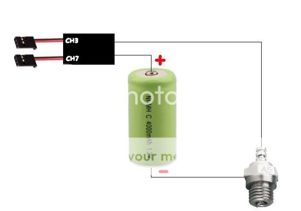
Aqui fica o esquema de ligações:
Here's the connection diagram:


